For some time now I have been working on my first CPU design as a hobby project. It started with a desire to learn more about CPU architecture design, and in particular instruction set architecture (ISA) design.
To be clear, I’m not a hardware or CPU designer by trade, but I have worked with performance critical software since the late 80’s, and I have done low level assembly code development on several different CPU architectures, including 8-bit CISC (6502), 16/32-bit CISC (68000) and 32-bit RISC (ARMv7). As far as possible I have stayed away from the abominable x86 ISA, but I have done a fair amount of SSE intrinsics coding in C/C++.
Edit: This article has been updated to reflect some changes to the ISA (e.g. register names).
Background
The initial idea was to make a very simple RISC CPU similar to the MIPS architecture. Early on, however, I realized that I needed to come up with a solution for floating-point and SIMD (single instruction multiple data) operations, so I looked at different contemporary solutions.
Being familiar with both x86 SSE/AVX and ARM NEON, I knew that they are hard to work with, set an upper limit to parallelism (due to a fixed SIMD register size), and are bolted on to an existing architecture as a fairly separate ISA (effectively creating different execution environment silos). Similarly almost every CPU architecture from the last four decades treat floating-point as a separate extension (e.g. via the coprocessor interface on the MIPS). In short, I wasn’t convinced that the prevalent ISA:s of today give the right answer to how integer, floating-point and SIMD instructions should work and interact with each other.
The turning point came when I learned more about the Cray-1 architecture from the mid 70’s. It was an epiphany! The Cray clearly had an architecture way ahead of its time, and in many respects the modern CPU industry is still trying to catch up with the ideas and inventions from that architecture:
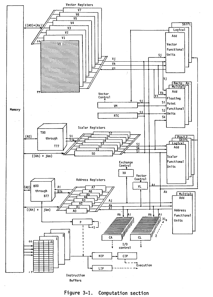
If you look closer at the diagram above, you can see that the Cray had a few interesting features not found in most modern architectures:
- A huge vector register file: Eight registers with 64×64 bits (4096 bits) in each register!
- There are no floating-point registers! Scalar and vector registers can hold both integer and floating-point values.
- Scalar and vector operands can be fed to the same execution units, and can even be mixed!
- There is a special vector length (VL) register that controls the length of vector operations. Unlike most current SIMD ISA:s, there is no need to split vector loops into a “main” (vector) and a “tail” (scalar) loop!
This inspired me to go for an ISA that borrows a mix of ideas from Cray-1 (the vector parts and the mixed float/integer register file parts) and MIPS (the RISC parts and the use-register-content-as-branch-condition part).
The MRISC32
After many iterations (but with much more work still remaining), an ISA and an accompanying CPU design is starting to take shape:
MRISC32 – “Mostly harmless Reduced Instruction Set Computer – 32-bit edition”
Documentation, code and tools can be found at GitLab: gitlab.com/mrisc32
So, what is it?
In essence, it’s a 32-bit RISC ISA designed with a holistic view on integer, floating-point, scalar and vector operations. In addition there is a hardware implementation of a single issue, in order, pipelined CPU. The hardware implementation mostly serves as an aid in the design of the ISA (at the time of writing the CPU is still incomplete).
Some key features are:
- 32-bit RISC instruction set.
- 32 32-bit scalar registers.
- 32 Nx32-bit vector registers (where N is typically 16 or more).
- All registers can hold integer or floating-point values.
- Variable length vector instructions.
- Almost all instructions can use either scalar or vector operands, or a mix of the two (including immediate scalar values).
- Branches are based on register content (there are no condition code flags).
Some of the design choices/consequences are described below.
A quick guide to the assembly language examples:
- Scalar registers are prefixed ‘r’.
- Vector registers are prefixed ‘v’.
- The leftmost operand is usually the destination operand, and the other operands are source operands.
- Most instruction names should be self explanatory. If not, see the MRISC32 Instruction Set Manual.
Integer and floating-point can be mixed
Since all registers can be used by both integer and floating-point instructions, you can easily use integer instructions for dealing with floating-point data.
Example: Load a floating-point value from memory and compute x = 2.0 * |x|.
    ldw   r13, [r7, #0]         ; Load a 32-bit word from addr [r7 + 0]
    and   r13, r13, #0x7fffffff ; Mask off the sign bit from the word
    fadd  r13, r13, r13         ; Calculate x = x + x (floating-point)
    stw   r13, [r7, #0]         ; Store the result back to memory
Vector and scalar operations can be mixed
Virtually all scalar instructions have identical vector instruction counterparts (one notable exception is branch instructions, which only exist as scalar operations).
Example: Add integer values.
    add   r12, r1, r2  ; Scalar operation: r12 = r1 + r2
    add   v12, v1, v2  ; Vector operation: v12 = v1 + v2
Most vector operations can use one scalar operand (even immediate values).
Example: Multiply all vector elements by the value in the scalar register R3 and bit-mask with 0x3ff0.
    mul   v12, v1, r3        ; Vector operation: v12 = v1 * r3
    and   v12, v12, #0x3ff0  ; Vector operation: v12 = v12 & 0x3ff0
Vector operations are variable length
The length of each vector operation (i.e. the number of vector elements to process) is determined by the scalar register VL.
Example: Perform a vector addition for three elements.
    ldi   vl, #3       ; Set the vector length to 3
    add   v12, v1, v2  ; v12 = v1 + v2 (first three elements)
The maximum vector length (i.e. the size of one vector register) is implementation dependent, and can be queried by reading the system register MAX_VL using the GETSR instruction. In a loop this can be conveniently combined with the MIN instruction to decide how many elements to process in each iteration.
Example: Process as many elements as possible per loop iteration.
    ; r1: Data array start address (32-bit floating-point elements)
    ; r2: Number of data elements (at least 1)
    getsr vl, #MAX_VL     ; VL = the maximum vector length
loop:
    min   vl, vl, r2      ; Vector length = min(max_vl, elements_left)
    sub   r2, r2, vl      ; Decrement the loop counter
    ldw   v8, [r1, #4]    ; Load elements into v8 (stride: 4 bytes/element)
    fmul  v8, v8, v8      ; Calculate the floating-point square (x = x^2)
    stw   v8, [r1, #4]    ; Store the elements back to memory
    ldea  r1, [r1, vl*4]  ; Increment the memory pointer (r1 = r1 + vl * 4)
    bgt   r2, loop        ; Loop if there are any elements left
Note that:
- This code will utilize maximum vector parallelism, regardless of the size of the vector registers of the CPU.
- No special tail loop is required to handle non vector sized operations.
Branches and conditions
One thing that sticks out is the compare & branch model. Unlike most architectures (x86, ARM, PowerPC, 68k, etc), but like MIPS and Alpha, the MRISC32 does not use condition code flags for keeping track of branch conditions. Instead any scalar register can be used as a branch condition.
Example: Loop as long as a loop counter is > 0.
    ldi  r12, #1234     ; Set the loop counter
loop:
    add  r12, r12, #-1  ; Decrement the loop counter
    ...
    bgt  r12, loop      ; Continue loop if the loop counter > 0
Example: Compare floating-point values and branch.
    fslt r12, r7, r8           ; Set r12 if r7 < r8
    bns  r12, not_less_than    ; Branch if r12 is not set
    ...
not_less_than:
One feature of the “compare and set” operations is that they produce a bit mask. I.e. “set” means all bits in the register are set to 1, whereas the opposite is that all bits are cleared to 0. This is a concept that has been inspired by SIMD ISA:s such as NEON and SSE. This makes the standard compare instructions useful for masking of vector registers too.
Example: Conditionally add elements of one vector register to another vector register.
    slt  v12, v7, #100   ; Set elements of v12 where v7[k] < 100
    and  v13, v7, v12    ; Clear (zero) elements that are >= 100
    add  v13, v13, v8    ; Add the masked vector to v8 and store in v13
Another side effect of the bit mask concept is that it works well with packed data types (see below). For instance it is possible to do packed compare-and-set operations on each byte of a word, and then branch if all, none or some of the packed bytes matched the condition.
Small data types are packed
This is the thing that I am the least satisfied with at the moment, since packed data is inherently cumbersome to work with, but it does have some advantages and at least it is semi-elegant.
In many instruction sets there are special mechanisms for working with data types that are smaller than the basic word size. For instance the 68000 had .B, .W and .L suffixes for treating each operand as 8, 16 or 32 bits, respectively. On the x86 you have special virtual registers to deal with sub-regions of a register (e.g. AX is the lowest 16 bits of EAX, which in turn is the lowest 32 bits of RAX). The RISC-V RV64I ISA has special instructions for doing 32-bit operations on 64-bit registers (e.g. ADDW, SRLW, etc).
In the MRISC32 ISA this kind of functionality is combined with increased parallelism by treating each 32-bit register as a container of packed smaller data types. To this end, many instructions support the following “packed” operation modes:
- Packed Bytes (.B): each 32-bit register/element is treated as four bytes (4 x 8 bits).
- Packed Half-Words (.H): each 32-bit register/element is treated as two half-words (2 x 16 bits).
- Unpacked: each 32-bit register/element is treated as a single 32-bit word.
Example: Perform packed byte operations: w = z * (x + y).
    add.b r12, r1, r2    ; 4 packed byte additions
    mul.b r12, r12, r3   ; 4 packed byte multiplications
In most situations the packed operations can be used for single byte or half-word sized operations too, by simply ignoring the unused sub-elements.
As a bonus, packed floating-point data types are supported too. “Packed Half-Word” translates into 2 x half-precision (16-bit floating-point) and “Packed Byte” translates into 4 x quarter-precision (8-bit floating-point).
Example: Perform packed half-precision floating-point operations: w = z * (x + y).
    fadd.h r12, r1, r2   ; 2 half-precision additions
    fmul.h r12, r12, r3  ; 2 half-precision multiplications
I’m still working on how to pack, unpack and convert between the different packed data types, but so far it seems to land in a reasonable set of instructions.
How about 64-bit support?
Simple answer: This is my first CPU design and I wanted to keep things simple, and I wanted to make sure that a CPU implementation would fit easily in a cheap FPGA. Thus I went for a 32-bit ISA.
On the other hand most of the concepts in the MRISC32 ISA are easily transferable to a corresponding 64-bit ISA (although some parts need to be redesigned).
One notable problem with the current MRISC32 ISA is that it does not support 64-bit floating-point, at all. The reason is that it would complicate the design too much. A reasonable solution might be to work with even:odd register pairs, but it would likely increase the number of register file read and write ports and complicate operand forwarding logic (or similar), etc.
Instead, it is anticipated that if/when a 64-bit MRISC ISA is developed, it will naturally support 64-bit floating-point (just as the Cray-1 did), and 32-bit floating-point would be implemented as a packed data type.
Status
The MRISC32 ISA is in constant development. Many pieces are still missing (interrupts, supervisor mode, memory management, cache management, multi-core support, etc, etc), but the parts that are there are starting to stabilize and are enough to run simple programs.
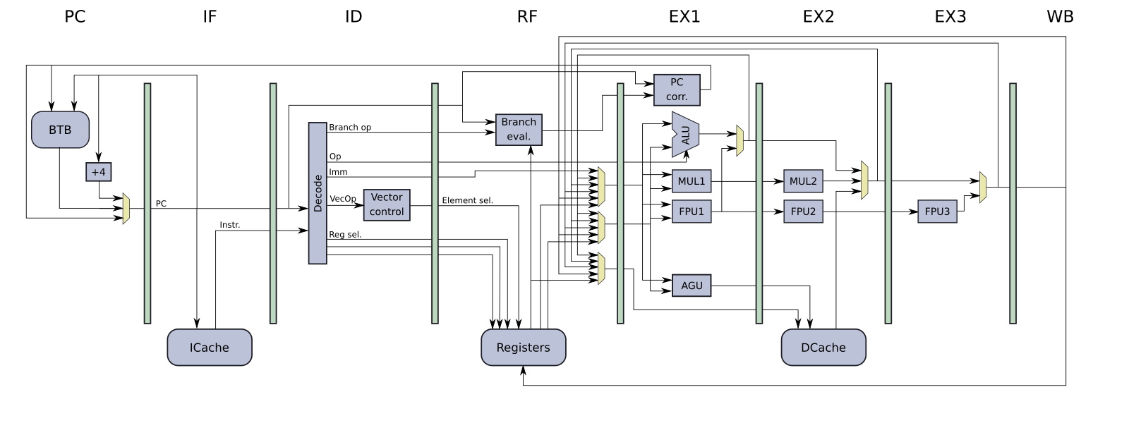
In the MRISC32 GitLab project you can find documentation, a CPU simulator (written in C++), a simple assembler written in Python (replaced by an MRISC32 port of binutils), and work-in-progress VHDL implementation of a pipelined MRISC32 CPU, called MRISC32-A1.
Here is a rough overview of the CPU pipeline:
As an example, the following (rather dull) image of a Mandelbrot fractal was generated by the MRISC32-A1 (VHDL simulation):

That’s about it for now. I’ll probably post more updates as I make more progress.
This is great! We need to *move forward* in computing and I love to see new ISAs and microarchitectures.
Question: When registers are able to hold both integers and floats, is there a performance or complexity cost? I don’t know much about the ground level engineering and physics here, but I assume floating point requires computational structures that integers don’t. Is that correct?
Random thoughts:
1. I think string processing is underappreciated, and I’d love to see instructions for string comparison like SSE 4.2 in the x86-64 ISA. Would these sorts of instructions break the RISC-ness of MRISC32?
Strings are treated as integers (or arrays of integers), and I wonder if it would pay off to treat strings as a basic type, either having string registers or registers that could hold strings, integers, and floats, with the recognition that strings ≠ integers. We’d know that various integer operations could not be performed on strings, and I wonder if that could give a performance advantage.
2. I wish we had UI primitives in our instruction sets. It’s extremely unclear to me how we get from these UI-unaware ISAs to a screen full of visually rich applications. I know GPUs have something to do with it, but most of the work is still actually coming from the CPU. I wonder what it would mean to have UI primitives in an ISA, what that would look like.
There’s no inherent cost of storing floating point in the same registers as integers (that’s how SSE/AVX/NEON/etc support both floating point and integer operations, for instance). On the contrary, I have found it to be simpler in a regular scalar architecture (which the MRISC32-A1 is). The registers don’t really care what data is stored in them, and the execution units don’t really care where it’s operands are coming from.
The situation may be different in a superscalar architecture (where register file traffic may be a limiting factor), but I have not come that far yet.
I think historically, FPUs were physically separate from the IU. Most of the current architectures were defined in the early to mid 1980’s, or late 70’s for 16-bit x86. So from a practical point of view, it made sense to have separate register files, as the FPU was a separate chip.
The Motorola 88000 (successor to the 68k) defined a combined IU/FP register file, though many consider this a mistake. Each read/wrote port added to the register file (required for super scaler access) adds (electrical) load and complexity to the register file, though I don’t know the details as hardware isn’t my thing.
Still, I personally like the idea of a combined IU/FP register file, it has a nice orthogonality, and the implementation details are probably not even that much of an issue anymore.
Interesting. I am working on a similar instruction set with variable vector length. My ISA is called ForwardCom. See http://www.forwardcom.info
I think that a global VL register is a problem for superscalar processors when different vectors have different lengths. During a task switch you have to save all vector registers with their maximum length even if they contain nothing. My approach is to give each vector register a tag with its length. In a register operation like v1 = v2 + v3, the destination will get the same vector length as the first source operand. With memory operands you have to specify the length explicitly using an extra scalar register operand to indicate the length.
My ForwardCom instruction set has many other interesting features. There is a discussion forum at http://www.forwardcom.info/forum
I’ll look into the ForwardCom ISA more closely (I’ve stumbled across it before, and it sounds very interesting). Actually, my plan is to add a vector length tag to each register (it’s hidden in the GitHub docs somewhere). As you suggest, writing to a vector register updates the register length (RL) to the vector operation length (VL), and if you read elements beyond the register length you get zeros. So the following code would effectively do a quick clear of a vector register:
ldi vl, 0
or v7, vz, vz
I have still not figured out how to efficiently deal with subroutine calls and interrupts, but the idea is that you should only need to store RL elements on the stack.
Many modern CPUs have more unlisted cores than one would think. When in doubt, make it asynchronous.
Although chances are, the most efficient way to deal with interrupts is located in a patent.
Since I like to think big I’d like to find a solution that allows for zero overhead regardless of the vector size (e.g. support 1024 vector elements, which equals 128 KB memory for the full register file -> not pretty for a regular stack push/pop).
One train of thought I’ve had leads to some sort of switchable set of register files (e.g. 4-16 copies), and then add a dedicated memory/bus/cache that a vector register file switcheroo-manager can use to asynchronously push/pop the LRU register file. Or similar… Not sure how it would actually work, but I think that something similar is required to transparently support low overhead task switching.
The “switchable set of register files” sounds a lot like the register windows used with the Sun SPARC architecture. If I am not mistaken, some people have attributed the difficulty of scaling the performance of the SPARC to match the competition to its use of register windows. May be worth thinking about.
Yes you risk eventually running into slow casing every thread switch when you run out of hw register sets. I think that the solution would have to be more like a cache to make it work well. For instance each thread could have a unique “register set id” (say, a 16-32 bit id), and in supervisor mode you can load/store a specific register set, which transparently swaps in data from a small local dedicated cache. The cache would asynchronously sync the cache with ram, using prediction techniques to have the most relevant register sets cached.
The Hitachi SH-4, the CPU used in the Dreamcast, had both vector and matrix operations – not nearly as well implemented as you’re planning, but it might be worth looking at if you haven’t already.
Ignorant programmer guy here: would such an architecture be suitable for processing audio streams/buffers?
Yes. It’s one of the best applications for this architecture, actually. It even has fixed point Q15 support, which is very common in audio DSP applications.
How did you very started in this space? What kind of documentation did you use or resources did you read?
First off, I have programmed assembly language on a few CPU architectures, I took a course in microprocessor design at the university (decades ago), and I programmed VHDL/FPGA as part of my master thesis.
For this particular project I studied a lot of different CPU architectures. The best architectures to study, IMO, are from the 60’s, 70’s and 80’s (you’ll find a greater diversity, and smaller and easier to grasp architectures). The RISC-V is also very interesting and well though through.
Google, find articles, blogs, old papers and manuals.
I hate the fact that you chose “dst, src” rather than “src, dst”.
In real life you’d tell someone to take something (src) and put it somewhere (dst), why make this illogical and unintuitive in assembler? Change the assembler before it’s too late!
You say you coded on MC68000 and that CPU has move.l src, dst. How could you do this, what posessed you to implement the retarded intel dst, src?!?
RISC (e.g ARM and MIPS) uses a variable number of source operands: one for move, two for math ops (usually). When a math op is in the for “a = a + b” (or “a += b”), the internal form is ADD R0, R0, R1, but the human-readable form can be condensed to ADD R0, R1, with R0 being assumed the destination and a source.
CISC (x86 and M68K) have no such: an ADD instruction always treats the destination register as a source register.
Ha ha! As you noticed I’m a 68k veteran, and for many years I hated assembler syntax with the destination operand to the left (I also hated little endian). However, with age comes wisdom I guess, and now I just go for the model that is most common since that is less likely to confuse people. And as others have said, thinking in math terms makes it more logical.
I’m not all that experienced with assembly, but my assumption was that having the dst first allowed you to trail with as many srcs as you want without special notation for the destination. so:
add dst1, src1, src2, src3, src4, src5, etc…
so: dst1=src1+src2+src3+src4+src5+…
am I wrong?
If you have a look at the instruction format at the top of mr32asm.py (each instruction is 32 bits), you’ll see that there is room for up to three operands (5 bits each, i.e. register 0-31). The orders in the instruction word and in the assembly syntax do not have to be the same, so it’s purely a syntactical decision. Since the convention for most 3-operand architectures (e.g. ARM) is to use “INSTRUCTION DST, SRC1, SRC2”, I used that aswell.
You could be funky – and this will look nice in the text editor with modern ligature programmer fonts like FiraCode…
‘Load v1 <- v0 + 5' is more readable than 'LD v1, v0, 5' for example.
as you say, it's just syntactic sugar on top of the real ISA, so no need to worry about funky short mnemonics and the like.
Add.pb v4 v4
Multiply.ph s0 <- s0, 5
odd, the comment got munged up… ah, the pointy brackets aren’t escaped by the commenting software.
‘Add.pb v4 <- v1, 8’ == ‘PBADD v4,v1,8’ == ‘Add.pb v1, 8 -> v4’
could all be accepted by the assembler.
You’re familiar with ARM NEON, which is somewhat compatible with the obsolete Vector Floating Point (VFP) extension. The VFP was available on the original Raspberry Pi’s BCM2835; I explored VFP programming here:
Part 1: Introduction
https://mindplusplus.wordpress.com/2013/06/25/arm-vfp-vector-programming-part-1-introduction/
Part 2: Examples
https://mindplusplus.wordpress.com/2013/06/27/arm-vfp-vector-programming-part-2-examples/
The Raspberry Pi 2 uses NEON by default, but supports 4 variants of VFP according to /proc/cpuinfo: vfp, vfpv3, vfpv4, and vfpd32. I have run vector-enabled code on my RPi2, and it generates correct results with no instruction exceptions.
Cool! I always wondered what the V in VFP meant. Nice explanations.
math is both logical and intuitive, and is used in real life:
A (dst) = B (src)
probably a silly question, how about Packed Nibbles (4 bits)? I know there are cases where calculating tiny numbers super fast is desirable, so for flexibility’s sake, why not?
Packed Nibble (PN/F): each 32-bit register/element is treated as eight nibbles (8 x 4 bits). / eighth precision
Packed Bytes (PB/F): each 32-bit register/element is treated as four bytes (4 x 8 bits). / quarter precision
Packed Half-Words (PH/F): each 32-bit register/element is treated as two half-words (2 x 16 bits). / Half precision
Unpacked: each 32-bit register/element is treated as a single 32-bit word.
I essentially have 2 bits (i.e. 4 combinations) in the instruction word to describe the packed mode. I decided to go easy and use only three of the combinations (leaving one for future use). It could get used for nibbles, but I doubt that it would be worth it. First of all there is no native 4-bit data type in popular languages (e.g. C), so no compiler would generate code for it. Second it might introduce undesirable hardware overhead to have that many sub-parts of a word.
On the other hand I was bold and let packed bytes be 8-bit floating point for floating point instructions. In terms of floating point, they are truly tiny numbers, but fast 😀 E.g. Microsoft uses something called “ms-fp8” for neural networks.
You could implement floating point numbers as posits for better range (e.g. 8 bit floats).
Yes I considered that, but I’d rather have IEEE 754 first. Posits could be added later.
I love this!
Someone was asking about string processing, and I agree that it’s one of the most important bread and butter tasks. I think your handling of packed data types is very cool! I actually found your page by asking about “string processing on 32-bit architectures” as I am inspired by Ben Eater’s breadboard CPU project on YouTube wondering how my ideal CPU would be designed.
So your way of dealing with packed data types (90% of strings in UTF-8 will be one byte per character) is already a 4 times speed-up by processing 4 characters in the same number of cycles that on wasteful UTF-16 or -32 representation (e.g. Java). Now I am considering throwing your vector registers at this problem! With your 32 x 32 vector registers, you would get to process strings in 128 character chunks.
Another use of this is bitmap processing with RGBA values that also fit neatly into 32 bits and you could add or multiply each byte individually.
Now bring this down to a nibble (4-bit) and implement BCD arithmetic? I guess BCD fell out of fashion somewhere in the 1980s, but in financial and database applications it would seem to be still a common thing, considering Oracle INTEGER and DECIMAL types and PostgreSQL’s bigint and big decimal. Java has those too.
Which brings me to another consideration. Graphics, ray tracing 3D, and video processing stuff are all well and good (though beyond both my expertise and interest), but speeding up data and symbolic processing is my interest. So, that packed data types go a long way already. Now what about more considerations of parallel processing pipelines. Thinking database join operations, and parallel execution of declarative and functional programming languages. What processor features would make a huge performance gain there? I’m still brainstorming about this …
So what is your road-map? Your CPU will be implemented on an FPGA or is there nowadays a way to produce custom chips?
… or maybe, instead of complicating things with BCD one might combine multiple registers of these vector fields to add with carry across more than one vector component? That way you could add 64 and 128 or higher integers. This might be useful for cryptographic operations like SHA-256, SHA-512, where your would combine 8 or 16 components in your 32×32 vectors.